How to Choose the Best Pressure Relief Manholes in 2026?
Choosing the right Pressure Relief Manholes in 2026 requires more than comparing prices, diameters, or delivery times. These access structures protect buried tanks and pipelines from dangerous pressure changes, vacuum conditions, gas accumulation, and unexpected maintenance loads. A suitable model should match the vessel’s operating pressure, surrounding soil, traffic class, corrosion exposure, and emergency venting requirements.
Dr. George Tchobanoglous, a widely recognized wastewater engineering authority, has stated, “Good design begins with understanding the system, not selecting equipment.” That principle remains highly relevant. Before selecting a manhole, engineers should review pressure calculations, flow behavior, groundwater levels, and the expected frequency of inspection. A stainless-steel cover may resist harsh chemicals, while a reinforced concrete chamber may better tolerate heavy vehicle loading. Gasket quality matters too. A small seal failure can become a serious operational problem.
Look closely at certification.
Manufacturers should provide test data, material specifications, load ratings, and installation instructions. Reliable suppliers also explain how their Pressure Relief Manholes perform during blocked vents, sudden surges, and repeated maintenance access. Field experience deserves attention here. Soil movement, poor drainage, and careless backfilling can reduce performance, even when the product itself is well engineered.
Not every “heavy-duty” label means the same thing. That is easy to overlook. Buyers should compare measurable performance instead of relying on attractive wording. The best choice balances safety, service life, inspection access, environmental resistance, and total ownership cost. Some decisions may still require revision after site testing. That is not failure; it is responsible engineering.
Define Tank Duty: API 650 Atmospheric Tanks Commonly Operate Below 2.5 psig
How to Choose the Best Pressure Relief Manholes in 2026?
Define Tank Duty: API 650 Atmospheric Tanks Commonly Operate Below 2.5 psig
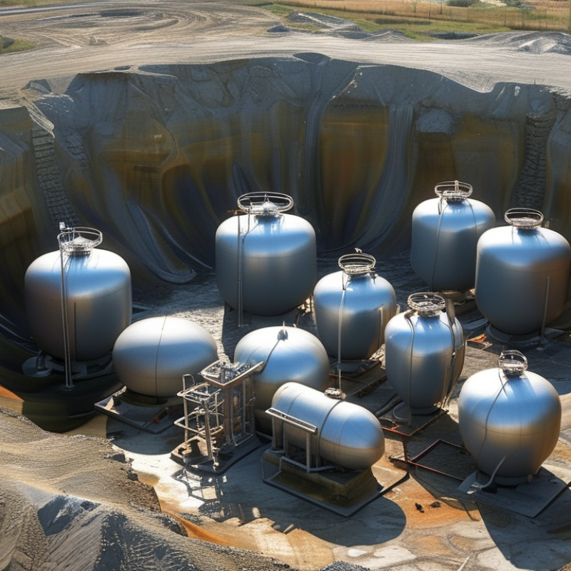
Selecting a pressure relief manhole starts with the tank’s actual duty. API 650 atmospheric tanks commonly operate below 2.5 psig. That figure is a design reference, not automatic permission to use any relief device. Product temperature, filling speed, emptying speed, and liquid volatility can change the pressure demand. A field review should compare operating data with the tank’s design pressure.
Look closely at normal breathing conditions. A tank may inhale air during a cold night or rapid discharge. It may exhale vapor during filling, heating, or blending. The manhole should provide suitable emergency relief without opening during routine fluctuations. Check the pressure and vacuum settings, flow capacity, gasket material, and connection size. A poor gasket choice can leak before the relief function becomes relevant. Small details matter.
Maintenance access also affects the decision. Choose a cover that workers can inspect safely, with clear lifting points and visible adjustment information. Confirm compatibility with the stored liquid and the site’s inspection program. Temperature swings deserve attention. They are often underestimated. Calculations should follow the tank standard, process data, and qualified engineering review. In practice, I would not select a manhole from pressure alone. That approach seems efficient, but it can overlook vacuum conditions, corrosion, or restricted vent paths. Document the assumptions, even the uncertain ones.
Calculate Relief Capacity Using API 2000 Normal and Emergency Venting Loads
How to Choose the Best Pressure Relief Manholes in 2026?
The right pressure relief manhole begins with the tank’s operating conditions. API 2000 provides a practical framework for calculating normal and emergency venting loads. Start with normal venting loads. These include liquid filling, product withdrawal, temperature changes, and atmospheric pressure changes. Solar heating can raise vapor pressure inside a dark tank within hours. Product vapor properties also affect the required capacity. Record the maximum filling rate, withdrawal rate, operating temperature, and allowable pressure or vacuum.
Emergency venting requires a separate calculation. Fire exposure may create rapid vapor generation and severe pressure rise. Other credible emergencies may include cooling system failure or abnormal gas introduction. Use the current applicable API 2000 edition and document every design assumption. Do not treat emergency capacity as a simple multiple of normal capacity. Calculate the required flow, then verify the manhole’s pressure setting, discharge path, and resistance to blockage. Small details matter.
In field reviews, I have seen large openings selected without checking actual certified capacity. Size alone proves very little. A 24-inch manhole may perform poorly if its cover lifts unevenly or its outlet creates excessive backpressure. Check test data, gasket compatibility, corrosion allowance, inspection access, and drainage around the seat. Confirm that normal and emergency devices can operate without interfering with each other. A spreadsheet may look exact while hiding uncertain inputs. Recheck those inputs against operating records, especially when the tank handles seasonal products or changing production rates. That lesson is easy to miss.
How to Choose the Best Pressure Relief Manholes in 2026? - Calculate Relief Capacity Using API 2000 Normal and Emergency Venting Loads
Illustrative engineering screening table for atmospheric and low-pressure storage tanks. Normal venting and emergency venting are evaluated as separate API 2000 design cases; final device capacity must be verified with the applicable API 2000 equations, certified manufacturer data, tank design pressure, vacuum rating, operating temperature, vapor properties, and installation losses.
| Design Basis |
API 2000 Venting Loads |
Manhole Geometry |
Selection Screening |
| Candidate |
Typical Tank Service |
Normal Inbreathing
(kg/h) |
Normal Outbreathing
(kg/h) |
Emergency Fire Case
(kg/h) |
Nominal Opening
(in) |
Nominal Opening
(mm) |
Geometric Area
(m²) |
Illustrative Pressure / Vacuum Setting |
Screening Result |
| Example design case: non-refrigerated atmospheric storage tank with hydrocarbon-compatible construction |
| A |
Low-viscosity liquid; low transfer rate |
850 |
1,200 |
4,800 |
18 |
457 |
0.164 |
+2.0 / −0.5 kPa |
Small opening; verify emergency capacity |
| B |
Routine liquid transfer; moderate vapor generation |
1,050 |
1,600 |
4,800 |
24 |
610 |
0.292 |
+2.5 / −0.5 kPa |
Verify normal and emergency flow rating |
| C |
Medium transfer rate; practical maintenance access |
1,200 |
2,000 |
4,800 |
30 |
762 |
0.456 |
+3.0 / −0.75 kPa |
Preferred screening option; confirm certified capacity |
| D |
High transfer rate; higher vapor displacement |
1,450 |
2,600 |
4,800 |
36 |
914 |
0.656 |
+4.0 / −1.0 kPa |
Suitable only when tank design pressure permits |
| E |
Large tank; high vapor displacement or rapid filling |
1,800 |
3,200 |
4,800 |
42 |
1,067 |
0.893 |
+5.0 / −1.0 kPa |
Use only after structural and vent-capacity review |
| Calculation reference for the geometry column |
| Geometric opening area |
A = π × D² ÷ 4, where A is area in m² and D is nominal diameter in m |
| Example normal design load |
Use the greater applicable API 2000 normal inbreathing or normal outbreathing requirement; do not assume both loads occur simultaneously unless the design basis requires it. |
| Example emergency design load |
Emergency fire exposure is shown as a separate 4,800 kg/h case. The actual emergency load must be calculated from tank dimensions, wetted area, insulation, heat input, liquid properties, and the applicable API 2000 method. |
| Capacity verification |
Select a manhole or venting assembly whose certified normal and emergency relieving capacities meet or exceed the governing calculated load at the specified pressure and vacuum settings, after accounting for inlet, outlet, flame-arrester, piping, and installation losses. |
|
Note: Nominal opening areas are geometric values calculated from nominal diameters and are not certified relief capacities. Pressure and vacuum settings shown are illustrative design points only. Confirm API 2000 applicability, tank mechanical design limits, operating conditions, material compatibility, corrosion allowance, inspection access, and local regulatory requirements before final selection.
|
Set Pressure and Vacuum Limits in kPa With a 10% Operating Margin
How to Choose the Best Pressure Relief Manholes in 2026?
Pressure relief manholes should match the tank’s real operating range, not a guessed number. Record normal pressure and vacuum in kPa during filling, discharge, cleaning, and temperature changes. A 10% operating margin gives the relief device room to remain closed during routine fluctuations.
For example, if a tank normally reaches 80 kPa, a pressure setting near 88 kPa may be suitable. However, never exceed the tank’s certified maximum pressure. For vacuum conditions, measure the negative pressure carefully. A normal vacuum of -4 kPa may require a vacuum setting around -4.4 kPa, based on the tank design and airflow demand. Check the sign and units twice.
Small details matter. Product viscosity, vent piping length, filter blockage, and sudden pump shutdown can change the actual pressure. I have seen a clean calculation fail because the measured gauge was installed too far from the manhole. Placement matters. Temperature also deserves attention, especially on tanks exposed to direct sunlight.
A neat 10% rule is useful, but it is not magic. Review the pressure-vacuum curve, emergency flow rate, gasket compatibility, and inspection access with a qualified engineer. Leave enough capacity for safe venting, while preventing unnecessary opening during normal work. Record the final setpoints clearly in kPa, including whether each value is gauge or absolute pressure. Confusion here can become expensive.
How to Choose the Best Pressure Relief Manholes in 2026?
Set pressure and vacuum limits in kPa with a 10% operating margin.
The chart compares typical operating conditions with recommended relief setpoints calculated using a 10% margin.
Positive values represent pressure relief settings, while vacuum values are shown as absolute vacuum magnitude.
Final settings should be verified against tank design pressure, temperature, fluid properties, venting capacity, and applicable engineering standards.
Verify API 650, API 2000, EN 14015, and ATEX Compliance Before Purchase
Before purchasing a pressure relief manhole in 2026, verify the exact standards cited by the supplier. API 650 addresses welded storage tank design and construction. API 2000 focuses on normal and emergency venting for atmospheric and low-pressure tanks. EN 14015 covers aboveground, vertical, cylindrical, welded steel tanks. These standards overlap, but they are not interchangeable. Confirm the manhole’s pressure, vacuum, material, gasket, and temperature ratings against the complete tank design.
Tips:
Request current certificates, drawings, test reports, and traceable serial numbers. Check the standard editions and national adoption requirements. For ATEX, confirm whether the complete assembly falls within the directive’s scope. Review equipment category, gas or dust zone, temperature class, and ignition protection method. A generic “ATEX-ready” statement is not sufficient evidence.
During technical review, compare the relief settings with API 2000 calculations, not only the product catalogue. Inspect flange dimensions, bolt materials, sealing surfaces, and corrosion allowances. Field experience shows that documentation gaps often appear after delivery. Some buyers accept a certificate with no product traceability. That is a weak decision. Also verify installation orientation and maintenance access. A compliant manhole can still perform poorly if the vent path is restricted. Ask an independent tank engineer to review conflicting requirements, especially when API and EN documents are used together. Minor uncertainty deserves investigation, not a hurried purchase.